Understanding (the Basics) of Safe Meter Usage
Multimeters, Volt Meters, Ammeters, Ohm Meters, Ohmmeters
Using an electrical meter safely and efficiently is perhaps the most valuable skill an electronics technician can
master, both for the sake of their own personal safety and for proficiency at their trade. It can be daunting at
first to use a meter, knowing that you are connecting it to live circuits which may harbor life-threatening levels
of voltage and current. This concern is not unfounded, and it is always best to proceed cautiously when using
meters. Carelessness more than any other factor is what causes experienced technicians to have electrical
accidents.
The most common piece of electrical test equipment is a meter called the multimeter. Multimeters are so
named because they have the ability to measure a multiple of variables: voltage, current, resistance, and
often many others, some of which cannot be explained here due to their complexity. In the hands of a trained
technician, the multimeter is both an efficient work tool and a safety device. In the hands of someone ignorant
and/or careless, however, the multimeter may become a source of danger when connected to a "live" circuit.
There are many different brands of multimeters, with multiple models made by each manufacturer sporting
different sets of features. The multimeter shown here in the following illustrations is a "generic" design, not
specific to any manufacturer, but general enough to teach the basic principles of use:
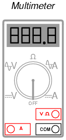
You will notice that the display of this meter is of the "digital" type: showing numerical
values using four digits in a manner similar to a digital clock. The rotary selector
switch (now set in the Off position) has five different measurement positions it can be
set in: two "V" settings, two "A" settings, and one setting in the middle with a funny-
looking "horseshoe" symbol on it representing "resistance." The "horseshoe" symbol
is the Greek letter "Omega" (Ω), which is the common symbol for the electrical unit of
ohms.
Of the two "V" settings and two "A" settings, you will notice that each pair is divided into
unique markers with either a pair of horizontal lines (one solid, one dashed), or a
dashed line with a squiggly curve over it. The parallel lines represent "DC" while the
squiggly curve represents "AC." The "V" of course stands for "voltage" while the "A"
stands for "amperage" (current). The meter uses different techniques, internally, to
measure DC than it uses to measure AC, and so it requires the user to select which
type of voltage (V) or current (A) is to be measured. Although we haven't discussed
alternating current (AC) in any technical detail, this distinction in meter settings is an
important one to bear in mind.
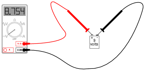
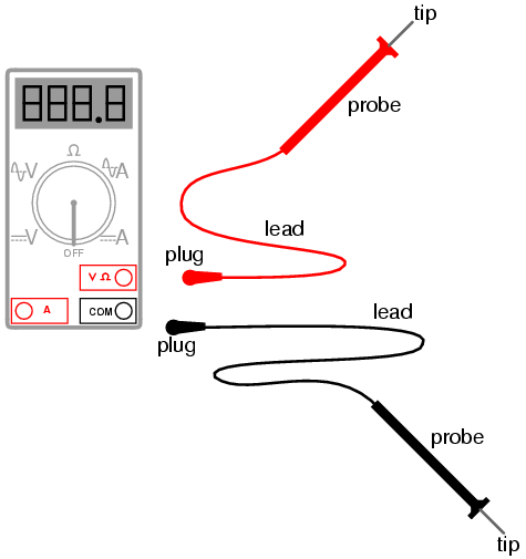
Note that the two test leads are plugged into the appropriate sockets on the meter for voltage, and the selector
switch has been set for DC "V". Now, we'll take a look at an example of using the multimeter to measure AC
voltage from a household electrical power receptacle (wall socket):
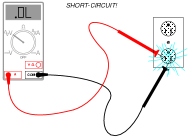
The only difference in the setup of the meter is the placement of the selector switch: it is now turned to AC "V".
Since we're still measuring voltage, the test leads will remain plugged in the same sockets. In both of these
examples, it is imperative that you not let the probe tips come in contact with one another while they are both in
contact with their respective points on the circuit. If this happens, a short-circuit will be formed, creating a spark
and perhaps even a ball of flame if the voltage source is capable of supplying enough current! The following
image illustrates the potential for hazard:
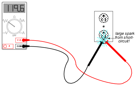
This is just one of the ways that a meter can become a source of hazard if used improperly.
Voltage measurement is perhaps the most common function a multimeter is used for. It is certainly the primary
measurement taken for safety purposes (part of the lock-out/tag-out procedure), and it should be well understood
by the operator of the meter. Being that voltage is always relative between two points, the meter must be firmly
connected to two points in a circuit before it will provide a reliable measurement. That usually means both probes
must be grasped by the user's hands and held against the proper contact points of a voltage source or circuit while
measuring.
Because a hand-to-hand shock current path is the most dangerous, holding the meter probes on two points in a
high-voltage circuit in this manner is always a potential hazard. If the protective insulation on the probes is worn or
cracked, it is possible for the user's fingers to come into contact with the probe conductors during the time of test,
causing a bad shock to occur. If it is possible to use only one hand to grasp the probes, that is a safer option.
Sometimes it is possible to "latch" one probe tip onto the circuit test point so that it can be let go of and the other
probe set in place, using only one hand. Special probe tip accessories such as spring clips can be attached to help
facilitate this.
Remember that meter test leads are part of the whole equipment package, and that they should be treated with the
same care and respect that the meter itself is. If you need a special accessory for your test leads, such as a spring
clip or other special probe tip, consult the product catalog of the meter manufacturer or other test equipment
manufacturer. Do not try to be creative and make your own test probes, as you may end up placing yourself in
danger the next time you use them on a live circuit.
Also, it must be remembered that digital multimeters usually do a good job of discriminating between AC and DC
measurements, as they are set for one or the other when checking for voltage or current. As we have seen earlier,
both AC and DC voltages and currents can be deadly, so when using a multimeter as a safety check device you
should always check for the presence of both AC and DC, even if you're not expecting to find both! Also, when
checking for the presence of hazardous voltage, you should be sure to check all pairs of points in question.
For example, suppose that you opened up an electrical wiring cabinet to find three large conductors supplying AC
power to a load. The circuit breaker feeding these wires (supposedly) has been shut off, locked, and tagged. You
double-checked the absence of power by pressing the Start button for the load. Nothing happened, so now you
move on to the third phase of your safety check: the meter test for voltage.
First, you check your meter on a known source of voltage to see that it's working properly. Any nearby power
receptacle should provide a convenient source of AC voltage for a test. You do so and find that the meter indicates
as it should. Next, you need to check for voltage among these three wires in the cabinet. But voltage is measured
between two points, so where do you check?
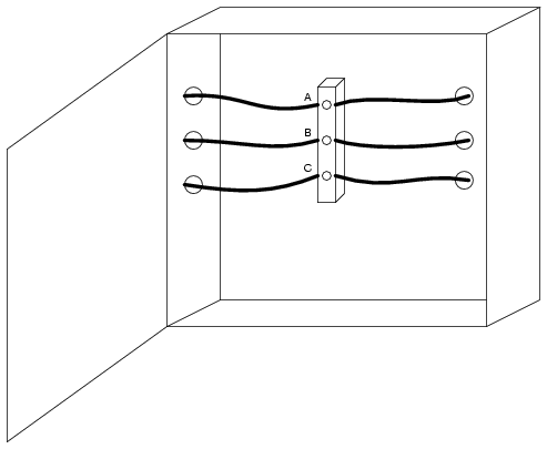
The answer is to check between all combinations of those three points. As you can see, the points are labeled "A",
"B", and "C" in the illustration, so you would need to take your multimeter (set in the voltmeter mode) and check
between points A & B, B & C, and A & C. If you find voltage between any of those pairs, the circuit is not in a Zero
Energy State. But wait! Remember that a multimeter will not register DC voltage when it's in the AC voltage mode
and visa-versa, so you need to check those three pairs of points in each mode for a total of six voltage checks in
order to be complete!
However, even with all that checking, we still haven't covered all possibilities yet. Remember that hazardous voltage
can appear between a single wire and ground (in this case, the metal frame of the cabinet would be a good ground
reference point) in a power system. So, to be perfectly safe, we not only have to check between A & B, B & C, and
A & C (in both AC and DC modes), but we also have to check between A & ground, B & ground, and C & ground (in
both AC and DC modes)! This makes for a grand total of twelve voltage checks for this seemingly simple scenario
of only three wires. Then, of course, after we've completed all these checks, we need to take our multimeter and
re-test it against a known source of voltage such as a power receptacle to ensure that it's still in good working order.
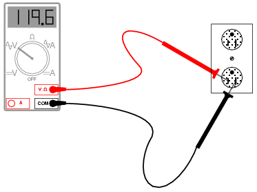
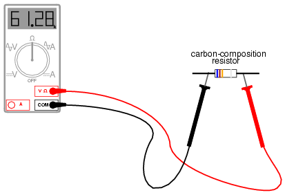
Using a multimeter to check for resistance is a much simpler task. The test leads will be kept plugged in the same
sockets as for the voltage checks, but the selector switch will need to be turned until it points to the "horseshoe"
resistance symbol. Touching the probes across the device whose resistance is to be measured, the meter should
properly display the resistance in ohms:
One very important thing to remember about measuring resistance is that it must only be done on de-
energized components! When the meter is in "resistance" mode, it uses a small internal battery to
generate a tiny current through the component to be measured. By sensing how difficult it is to move this
current through the component, the resistance of that component can be determined and displayed. If
there is any additional source of voltage in the meter-lead-component-lead-meter loop to either aid or
oppose the resistance-measuring current produced by the meter, faulty readings will result. In a worse-
case situation, the meter may even be damaged by the external voltage.
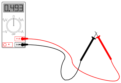
The "resistance" mode of a multimeter is very useful in determining wire continuity as well as making
precise measurements of resistance. When there is a good, solid connection between the probe tips
(simulated by touching them together), the meter shows almost zero Ω. If the test leads had no resistance
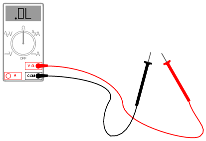
in them, it would read exactly zero:
If the leads are not in contact with each other, or touching opposite ends of a broken wire, the meter will indicate
infinite resistance (usually by displaying dashed lines or the abbreviation "O.L." which stands for "open loop"):
By far the most hazardous and complex application of the multimeter is in the measurement of current. The reason
for this is quite simple: in order for the meter to measure current, the current to be measured must be forced to go
through the meter. This means that the meter must be made part of the current path of the circuit rather than just be
connected off to the side somewhere as is the case when measuring voltage. In order to make the meter part of the
current path of the circuit, the original circuit must be "broken" and the meter connected across the two points of the
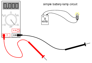
open break. To set the meter up for this, the selector switch must point to either AC or DC "A" and the red test lead
must be plugged in the red socket marked "A". The following illustration shows a meter all ready to measure current
and a circuit to be tested
|
Now, the circuit is broken in preparation for the meter to be connected:
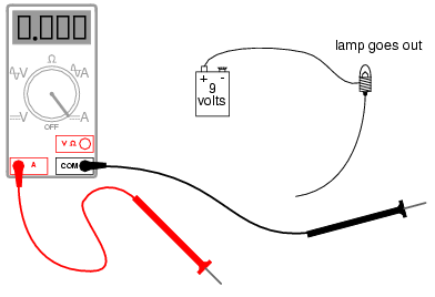
The next step is to insert the meter in-line with the circuit by connecting the two probe tips to the broken ends of the
circuit, the black probe to the negative (-) terminal of the 9-volt battery and the red probe to the loose wire end
leading to the lamp:
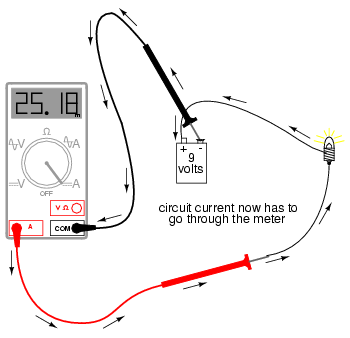
This example shows a very safe circuit to work with. 9 volts hardly constitutes a shock hazard, and so there is little to
fear in breaking this circuit open (bare handed, no less!) and connecting the meter in-line with the flow of electrons.
However, with higher power circuits, this could be a hazardous endeavor indeed. Even if the circuit voltage was low,
the normal current could be high enough that am injurious spark would result the moment the last meter probe
connection was established.
Another potential hazard of using a multimeter in its current-measuring ("ammeter") mode is failure to properly put it
back into a voltage-measuring configuration before measuring voltage with it. The reasons for this are specific to
ammeter design and operation. When measuring circuit current by placing the meter directly in the path of current,
it is best to have the meter offer little or no resistance against the flow of electrons. Otherwise, any additional
resistance offered by the meter would impede the electron flow and alter the circuit's operation. Thus, the
multimeter is designed to have practically zero ohms of resistance between the test probe tips when the red probe
has been plugged into the red "A" (current-measuring) socket. In the voltage-measuring mode (red lead plugged
into the red "V" socket), there are many mega-ohms of resistance between the test probe tips, because voltmeters
are designed to have close to infinite resistance (so that they don't draw any appreciable current from the circuit
under test).
When switching a multimeter from current- to voltage-measuring mode, it's easy to spin the selector switch from the
"A" to the "V" position and forget to correspondingly switch the position of the red test lead plug from "A" to "V". The
result -- if the meter is then connected across a source of substantial voltage -- will be a short-circuit through the
meter!
|
To help prevent this, most multimeters have a warning feature by which they beep if ever there's a lead plugged in
the "A" socket and the selector switch is set to "V". As convenient as features like these are, though, they are still
no substitute for clear thinking and caution when using a multimeter.
All good-quality multimeters contain fuses inside that are engineered to "blow" in the even of excessive current
through them, such as in the case illustrated in the last image. Like all overcurrent protection devices, these fuses
are primarily designed to protect the equipment (in this case, the meter itself) from excessive damage, and only
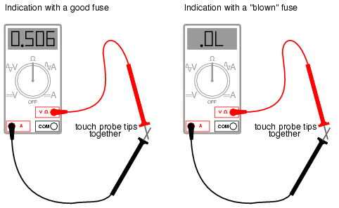
secondarily to protect the user from harm. A multimeter can be used to check its own current fuse by setting the
selector switch to the resistance position and creating a connection between the two red sockets like this:
|
A good fuse will indicate very little resistance while a blown fuse will always show "O.L." (or whatever indication that
model of multimeter uses to indicate no continuity). The actual number of ohms displayed for a good fuse is of little
consequence, so long as it's an arbitrarily low figure.
So now that we've seen how to use a multimeter to measure voltage, resistance, and current, what more is there to
know? Plenty! The value and capabilities of this versatile test instrument will become more evident as you gain skill
and familiarity using it. There is no substitute for regular practice with complex instruments such as these, so feel
free to experiment on safe, battery-powered circuits.
REVIEW:
- A meter capable of checking for voltage, current, and resistance is called a multimeter, As voltage is always
relative between two points, a voltage-measuring meter ("voltmeter") must be connected to two points in a
circuit in order to obtain a good reading. Be careful not to touch the bare probe tips together while measuring
voltage, as this will create a short-circuit!
- Remember to always check for both AC and DC voltage when using a multimeter to check for the presence
of hazardous voltage on a circuit. Make sure you check for voltage between all pair-combinations of
conductors, including between the individual conductors and ground!
- When in the voltage-measuring ("voltmeter") mode, multimeters have very high resistance between their
leads.
- Never try to read resistance or continuity with a multimeter on a circuit that is energized. At best, the
resistance readings you obtain from the meter will be inaccurate, and at worst the meter may be damaged
and you may be injured.
- Current measuring meters ("ammeters") are always connected in a circuit so the electrons have to flow
through the meter.
- When in the current-measuring ("ammeter") mode, multimeters have practically no resistance between their
leads. This is intended to allow electrons to flow through the meter with the least possible difficulty. If this
were not the case, the meter would add extra resistance in the circuit, thereby affecting the current.
Our thanks to:
Lessons In Electric Circuits copyright (C) 2000-2004 Tony R. Kuphaldt, under the terms and conditions of
the Design Science License. DESIGN SCIENCE LICENSE
Copyright © 1999-2000 Michael Stutz [email protected]
Verbatim copying of this document is permitted, in any medium. |
|
|
|
|
|
If you've found our website helpful, and you are into Ohm's law or have a need for any gifts for your employees, coworkers, relatives, etc. please view our complete Electrical Worker's Gift Store while you're here. We thank you!
|