The Basics (and more) of Resistors!
Understanding Resistors / Resistor Band Charts - Color Code Coding Charts
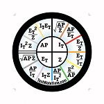
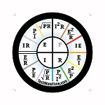 TechNote for resistor band color card or chart on our watch and clock products: A copy of how to read the our "Magic Wheel" or "Power Wheel" resistor band color chart will be included with your ohm's law watch or clock when it is shipped to you, along with warranty info. TechNote for resistor band color card or chart on our watch and clock products: A copy of how to read the our "Magic Wheel" or "Power Wheel" resistor band color chart will be included with your ohm's law watch or clock when it is shipped to you, along with warranty info.
The color at each hour on your Ohm's law product is purposely positioned at the number of that color’s value. This will help you to identify the value for each resistor. For example, the 12:00 black band position represents the value of “0"; the 1:00 brown represents the value of “1"; and so on consecutively up to the 9:00 “white” representing the value of “9". The 10:00 silver (or 10 min. to) represents 10% tolerance, and the 11:00 gold band position (or 5 min. to) represents 5% tolerance. With this in mind you should be able to read the resistor bands for easy identifying. For more on resistors, and how to read resistor band colors, please go to our resistor page:
Our Ohm's law watch and clock products are great for ham radio operators, students studying electronics or electrical theory, electrician's, troubleshooters, engineers, apprentices, master electrician's, electrical contractors, college classrooms, and anyone in the electrical and electronics fields! We hope you find our products helpful in the office and in the field.
Where Resistors are Used:
Resistors are the most common of the electronic components. They are used in all applications where a current must be limited or a voltage steps down.
In electronic circuits the main application for resistors is in bias or stepping down a voltage. Many elements of a circuit must operate with voltages lower than supplied by the power supply. This means that resistors must be used to step down the voltage to the desired value. These resistors are called bias resistors.
Resistor Color (Colour) Bands Codes Chart Wheel
Black ...........0.....................0................... ..1
Brown...........1.....................1....................10
Red..............2.....................2...................100
Orange........3......................3................1,000
Yellow...........4.....................4..............10,000
Green...........5.....................5............100,000
Blue..............6.....................6...... ...1,000,000
Violet............7.....................7........10,000,000
Gray.............8.....................8.... .100,000,000
White............9.....................9...1,000,000.000
Note that the 4th band indicates tolerance (accuracy)
Gold...................................................0.1.......................+-5%
Silver................................................0.01.....................+-10%
None.............................................................................+-20%
|
Resistor Color Code Chart Basics:
In the colour code system of marking, three colors are used to indicate the resistance value in ohms, and a fourth color is sometimes used to indicate the tolerance of the resistor. By reading the colors in the correct order and by substituting numbers from the color code, you can immediately tell all you need to know about a resistor.
First significant figure: On the resistor, the color of the first band indicates the first digit of the resistance value. For example is this band is brown, the first digit is 1 (refer above).
Second significant figure: The color of the second band on the resistor indicates the second digit of resistance value. For example, if this band is green, the second digit is 5.
Multiplying Value: The color of the third band indicates the value by which the first two digits are to be multiplied to obtain the resistance value. For example, again using the color bode chart above, is this band is yellow, the first two digits are multiplied by 10,000. (Therefore, with first and second significant digits of 15, the value is 150,000). This third band can also be thought of as indicating the number of zeros to be added after the second digit. For example, if this band is blue, add six zeros after the second digit; but if the band is black, no zeros are added.
Tolerance: The color on the fourth band indicates the tolerance of the resistor. Please refer to above chart.
|
Resistance: Property of an electric conductor by which it opposes a flow of electricity and dissipates electrical energy away from the circuit, usually as heat. Optimum resistance is provided by a conductor that is long, small in cross section, and of a material that conducts poorly. Resistance is basically the same for alternating and direct current circuits (see impedance). However, an alternating current of high frequency tends to travel near the surface of a conductor. Since such a current uses less of the available cross section of the conductor than a direct current, it meets with more resistance than a direct current. In circuit analysis an ideal resistor, i.e., a circuit component whose only property is resistance, is called a resistance. The phenomenon of resistance arises from the interactions of electrons with ions in the conductor. The unit of resistance is the ohm.
The preceding was a courtesy of:
"resistance, in electricity." The Columbia Electronic Encyclopedia.
© 1994, 2000-2005, on Fact Monster.
© 2000–2005 Pearson Education, publishing as Fact Monster.
08 Apr. 2005 <http://www.factmonster.com/ce6/sci/A0841587.html> .
Types of Resistors:
Resistors are classified into fixed or variable resistors.
The most commonly used resistors are carbon composition and carbon film types, where the resistive element is a thin layer of carbon strips deposited onto a ceramic rod. Another type is the metal film resistor or film resistor, with the same external aspect as the carbon type. In this type, metal is evaporated onto ceramic rods forming a thin film. These resistors are cheap and can be easily fabricated in a large range of values. They are intended for applications in low-power or small-current circuits. The disadvantage of carbon resistors is that they are noisy.
When desiring resistors that can operate with large currents, the wirewound type is preferred. Those resistors are formed by turns of metal wires (allows such as nickel, chromium, iron, silver, etc.) onto a ceramic rod. The materials, gauge, and number of turns determine the amount of resistance, the size, and how much heat they can handle.
Fixed Resistors:
Fixed resistors, or common resistors, is a component made from some conducting material the size, shape, and conductivity of which are arranged to determine the amount of electrical resistance needed. The amount of resistance is measured in ohms.
Specifications:
When replacing or testing any electronic device it is necessary to know its specifications. The main specifications for resistors are:
- Value: The value is the amount of resistance in ohms of a resistor. In large-size types the resistance can be found on the body of the device. But in smaller types there isn't enough space to display the resistance value. In this case a color code is used. Color bands or stripes are printed on the resistor body. Accordingly, the position in the equipment is part of the meaning of a band. Combining the two, the resistance value of any resistor can be found. In addition to the value in ohms, the color bands also indicate the tolerance of the component.
- Dissipation: The size and the material the resistor is made of determines how much heat it can produce without burning. Based on the application the resistors are to be used for, resistors must be chosen in different sizes or dissipation capacities.
- Tolerance: It is impossible to manufacture a resistor with an exact value of resistance. This is not necessary as the electronic circuits are designed to operate within a certain band of value of components and voltages. The difference between the value specified for a component and the real value or measured value is called tolerance.
Variable Resistors:
In many applications something in a circuit can be controlled or adjusted by changing a resistance. You can increase the volume of an amplifier or the brightness of a lamp by altering the current in a circuit. The common way to alter currents and voltages in a circuit is altering a resistance placed in the circuit for this task. The principal component that can be used to make this happen is the variable resistor. As the name indicates, a variable resistor is a device presenting a resistance that can be changed. There are two types of variable resistors. One allows the resistance value to be changed easily and often, like the volume of an amplifier. The other is the semi-fixed resistor that ordinarily doesn't change the resistance value. It is used to adjust the operational condition of the electronic circuit.
Basically, variable resistors are formed by a resistive material (metal or carbon) with a cursor sliding onto it.
Specifications:
There are two basic types of variable resistors: potentiometer or trimmer potentiometer. Potentiometers (slide and rotary) are used to control many functions of equipment, such as volume, dimmers or can include switches to turn on and off an appliance.
- Value or Nominal Resistance: The most important specification in a variable resistor is the nominal resistance. This resistance is indicated by ohms and represents the maximum value of resistance assumed by the component.
- Variation of Resistance: In some applications the way the resistance changes when the potentiometer is adjusted is important. There are basically two types of variation of resistance curves: linear and logarithmic.
Total resistance is always less than the smallest resistor RT = 1/(1/R1 + 1/R2 + 1/R3 +.......
- Total current is equal to the sum of the currents of all parallel resistors
- Total power is equal to the sum of power of all parallel resistors
- Voltage is the same across each of the parallel resistors
Series Circuits:
- Total resistance is equal to the sum of all the resistors
- Current in the circuit reamins the same through all the resistors
- Voltage source is equal to the sum of voltage drops of all resistors
- Power of the circuit is equal to the sum of the power of all resistors
Basic Terminology:
Circuit: A closed path followed or capable of being followed by an electric current. A configuration of electrically or electromagnetically connected components or devices.
Component: A part of an electrical complex, such as a resistor.
Conductor: A substance or medium that conducts heat, light, sound, or especially an electric charge. (NOTE: The common resistor or fixed resistor is a component made from some conducting material the size, shape, and conductivity of which are arranged to determine the amount of electrical resistance needed. The amount of resistance is measured in Ohms.)
Current: The amount of electric charge flowing past a specified circuit point per unit time
Dissipate: To cause to lose (energy, such as heat) irreversibly.
Kilohm: The unit of resistance equal to 1,000 ohms, abbreviated 1K
Megaohm: The unit of resistance equal to 1,000,000 ohms, abbreviated IM or 1 meg.
Ohm: A unit of electrical resistance equal to that of a conductor in which a current of one ampere is produced by a potential of one volt across its terminals.
Ohmmeter: Meter used to measure resistance directly.
Reactance: Opposition to the flow of alternating current caused by the inductance and capacitance in a circuit rather than by resistance.
Resistor: A device used to control current in an electric circuit by providing resistance. (NOTE: Devices that add resistance to a circuit can be used to limit or reduce the current flow or to step down a voltage - two functions are very important in electronic circuits. To add an amount of resistance to a circuit or reduce the flow of electric current by a circuit, components called resistors are used. Inside electronic equipment are resistors of many types and sizes with resistance values ranging from less than 1 ohm to many million ohms. Resistors are found in many sizes and shapes according to the amount of resistance they present, some special performance feature they must have, and the amount of heat generated when working)
Resistor Color Code: A series of color bands on a carbon resistor that tells what the resistance and tolerance of the resistor are.
Resistor Tolerance: The spread in value of a resistor about its designated value.
Resistance: The opposition of a body or substance to current passing through it, resulting in a change of electrical energy into heat or another form of energy. The amount of resistance is measured in Ohms. (NOTE: The presence of resistance in an electric circuit is not desirable. Only when electric power must be transformed into heat such as in air heaters, water heaters, and electric showers, are elements present with an electric resistance to the current flow used. Forcing passage through those elements allows the current flow to produce heat.)
Tolerance: Decreased responsiveness to a stimulus, especially over a period of continued exposure.
Value: The amount of resistance in ohms of a resistor.
 Please check out our other categories while you're at our website. We offer products in addition to content! Products such as Ohm's law watches, clocks, charts, decals and Ohm's law coins! We offer other electrician's and engineer's gifts such as window decals, funny full color decals, posters, mugs, jewelry, greeting cards, etc. Just click on any of our gift departments to the left. Thank you! Please check out our other categories while you're at our website. We offer products in addition to content! Products such as Ohm's law watches, clocks, charts, decals and Ohm's law coins! We offer other electrician's and engineer's gifts such as window decals, funny full color decals, posters, mugs, jewelry, greeting cards, etc. Just click on any of our gift departments to the left. Thank you!
|